

Introduction: Touch Tone MIDI Phone


Repurposing obsolete technology will not only give new life to a devices otherwise bound for the dump, but will also provide the investigative mind some insights in the history of a bygone era.
This project takes a vintage touch tone phone and converts it into a musical instrument, or more specifically, a MIDI controller using the push-buttons to generate the signals for musical notes.
Here is the source code for the Arduino sketch.
Supplies


Hardware
- Southwestern Bell Freedom Phone Model No: FT325
- Found this vintage device at a thrift-store five or six years ago. It was in usage as a kids toy since then, but appears no worse for wear. There are many phones of a similar type that could be repurposed in the same way.
- Arduino Diecimila
- This is almost a vintage piece of hardware itself. It was sitting unused so it was nice to get it into a project. More or less any microcontroller board could be substituted if it has enough GPIO pins. 10 pins for the push buttons, and the TX pin for the MIDI. 4 pins for the LEDs
- 2 pins for additional buttons (Redial, Pulse/Tone switch)
- Prototype Shield
- Hook-up wire
- MIDI jack, 5-Pin female
- 1/4" output jack - output microphone signal to line-level
- USB Type B short extension cable
Tools
- Prototype breadboard
- Soldering iron and wire
- Multimeter
- Plastic cutting tools
- Dremel rotary tool
- Jeweler's saw
- Nibbler
Step 1: Phone Deconstruction


What makes these phones tick? Or perhaps more appropriately - ring? The first step is to carefully begin taking it apart.
Removing the upper shell of the case is a simple matter of unscrewing three bolts from the base - uncovered beneath is a trip to the past. A pair of solenoid ringers which, when activated with 75-90 v AC at 20 Hz, let anyone in a mile radius that someone is calling. After hooking one of these up to a 30VDC workbench power supply, it made a single, yet satisfying, "thunk". These were later removed to have space to mount the new electronics. It has through-hole circuit board technology - none of that new fangled surface mount business. Only a few IC chips. But most importantly, at least for this project - the push button keypad.
Step 2: Mapping Button and Wires


The keypad is connected to the circuit board via a ribbon cable. Either clipping or desoldering this will work, either way, it is now necessary to find which wire or wire combinations are connected to which button.
After some trial and error (and internet research), it was evident that each button would complete a circuit between two of the wires. For instance, when the 1 button is pressed, then electrical current is permitted to flow between wire #1 and #8. This can be tested on a multimeter using the "continuity beep" mode. Attach the two test leads to wires, and if a beep is heard when pressing a button, then this is a successful mapping between that button and the pair of wires.
There are 11 total wires which could be combined in 55 unique combinations, each of which could be the mapping for any of the 12 buttons. So it was necessary to make a chart of these mappings. To speed it up a bit, a makeshift testing apparatus was constructed. And makeshift it was - a screwdriver and heavy-ish solder spool balanced on top of a button while testing the wires with the multimeter leads. However goofy it looks, it worked - and soon revealed a pattern.
Wires numbered #1, #2, and #4 are associated with the first, second, and third rows on the keypad. Similarly, wires #8, #7, and #5 are tied to the first, second and third columns. Combined this makes a matrix of button addresses. The star and pound keys have their own wires - #2 and #6 for the *star, and #9 and #10 for the #pound. Wire #11 seems to be unused.
It's interesting to note that the matrix of rows and columns will simplify the circuitry to generate the dual-tones used in the phone system when dialing numbers. Looking at the DTMF keypad frequencies table, each column and each row are assigned a frequency which are combined to generate the distinctive tones for each button. The star and pound being on their own wires when they could easily be added to the matrix is curious - perhaps to allow the time travel circuitry to function?
Step 3: Enter the Arduino


Now that the wiring is known, the next task is to get the keypad connected to the Arduino. This means wiring each of the wires to a GPIO. A convenient way to go about this is to plug the keypad wires into separate rows on a project breadboard, then to use jumper wires to connect each to an Arduino pin.
Open a new sketch in the Arduino IDE and define the button mapping for the keypad to GPIO pins from the previous step. Note that these are shifted +1 from the wire numbers in the previous step (GPIO pins 2 - 11) avoiding the TX and RX communication pins which will be needed for MIDI output.
#include "MatrixButton.h"

// input-output pin combinations for all the keypad buttons
MatrixButton keypad[] = {
  {2, 9},    /* 1 */  {2, 8}, /* 2 */  {2, 6}, /* 3 */
  {4, 9},    /* 4 */  {4, 8}, /* 5 */  {4, 6}, /* 6 */
  {5, 9},    /* 7 */  {5, 8}, /* 8 */  {5, 6}, /* 9 */
  {10,  11}, /* * */  {7, 8}, /* 0 */  {7, 3}  /* # */
};
(The MatrixButton source is here. Looking for a suitable already-existing library to handle this function did not yield results - if you know of one, don't hesitate to share)
It's convenient to have immediate feedback on the pressed/released state of the buttons, so add an LED to another digital pin with a resistor like in this Instructable. Add a variable for the pin it is on:
// LED pin
int led = 13;
Then initialize the pins in the setup() function
void setup() {
  // initialize keypad button states
  for (byte i = 0; i < 12; i++)
      keypad[i].begin();

  // init the LED
  pinMode(led, OUTPUT);
}
At each consecutive run of the loop, the state of each wire combination is scanned, checking for pressed or released buttons. If any of them are in the pressed state, then set the led to turn on, otherwise turn it off.
void loop() {
  bool anyPressed = false;

  // scan keypad for key presses
  for (byte i = 0; i < 12; i++)
  {
    bool hasChanged;
    bool state = keypad[i].read(hasChanged);

    if (state == MatrixButton::PRESSED)
      anyPressed = true;
  }

  // light up the LED if one (or more) buttons are pressed
  if (anyPressed)
    digitalWrite(led, HIGH);
  else
    digitalWrite(led, LOW);
}
Test each button to ensure it is wired correctly and activating the LED. If there are any problems, it can be helpful to write debug messages using the serial write functions, viewable in the Arduino IDE.
Here is the code snippet.
Step 4: Let the MIDI Play


Wire up the MIDI jack to the project breadboard following this diagram from these instructions. Since only MIDI output is being used, only 3 of the MIDI jack's 5 pins are used. The Arduino sends the MIDI data through the TX GPIO - pin number 1.
Back in the Arduino IDE, add the MIDI library using the Arduino Library Manager and add initialization code to the sketch.
#include <MIDI.h>
// ...
byte midiChannel = 1;

MIDI_CREATE_DEFAULT_INSTANCE();

void setup() {
  // ...

  MIDI.begin();
}
Define a musical scale to map to the keypad's buttons. Here is a pentatonic scale - 5 harmonious tones in each octave - plus the major 7th semitone. Starting with C as a root note, this will be scale of C, D, E, G, A, B played on the top two rows of the keypad. Adding 12 to each value for the bottom rows creates a two octave range. This is a fun part to experiment with adding interesting scales.
// musical scale in semitones, pentatonic + maj 7
const int8_t music_scale[12] = {
  0, 2, 4,
  7, 9, 11,
  12, 14, 16,
  19, 21, 23
};
Now it is ready to send MIDI notes when any buttons on the keypad are pressed. Each button is scanned as before. However, if it has been changed to the pressed state, then the corresponding tone from the scale array is played. The value of 60 being added to the tone is "Middle C" note in MIDI. Each of the values in the array is then treated as an offset from this root note, creating the desired scale.
void loop() {
  // scan keypad for key presses
  for (byte i = 0; i < 12; i++)
  {
    bool hasChanged;
    bool state = keypad[i].read(hasChanged);

    if (hasChanged)
    {
      if (state == MatrixButton::PRESSED)
        MIDI.sendNoteOn(60 + music_scale[i], 127, midiChannel);
      else
        MIDI.sendNoteOff(60 + music_scale[i], 0, midiChannel);
    }
  }
}
The last step is to turn off the notes so they don't play forever. This is done by sending a corresponding "note off" MIDI instruction after the button is released.
Here is the complete code snippet.
Step 5: Blinkenlights

This phone features four status LEDs which are available to be repurposed as status indicators. This seems to be a rare feature for this type of phone - must be the executive model.
Carefully solder positive and negative wires to exposed areas of the pins. Then connect these with the Arduino with a resistor in the circuit. Test a few variety of ohm for each color to find a good brightness.
To create blinking patterns to indicate status, the Arduino-Blinkenlight library is a great choice.
Step 6: Drop the Mic


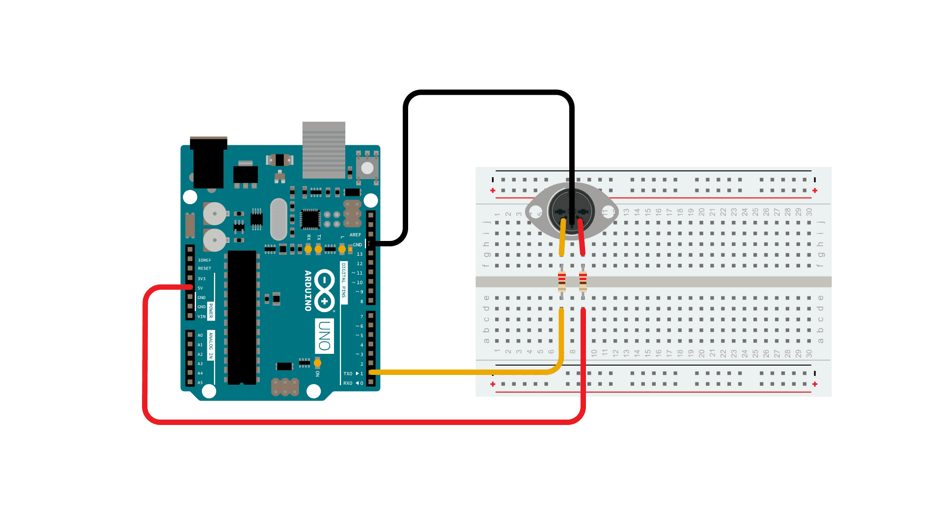
Since this phone will now be a musical device, it seems fitting to hook up the handset's microphone so it can be amplified. These phones use a electret microphone which require a small amount of power to capture acoustics. This page has a tutorial on how it is designed and how to connect it to a line level signal. Also, here is an entertaining video on these mics and some other strategies for reducing line noise.
Of note - the yellow and black lines on the jack inside the phone are those which connect the microphone at the bottom of the handset - red and green are the speaker. To provide power for the mic, the Arduino's 3.3V pin is used to along with a 2.2k resistor to bring the voltage down.
To have the microphone activate only when the handset is lifted out of the cradle, hook the switch attached to the cradle to the power circuit. This is a very simple way to keep the microphone disabled when it is not "on air".
Step 7: Wire It Up


To move this project from the breadboard to the phone, all the components were transferred to an Arduino shield and connected to the phone wires using 2.54mm JST XH connectors. If ever doing this again, it'd be a good improvement to learn how to design and order a PCB.
After all connections are soldered and tested, it is attached to the base of the phone with a 3mm bolt. The ringers had to be removed, and about a third of the original circuit board had to be removed with a jeweler's saw to make room. It is also important to ensure enough vertical space for the cradle switch to depress without being blocked by wiring.
Step 8: Encase


To provide cable connections when the top shell is replaced, it is necessary to cut some of the material on the case. This requires some planning to place the jacks in locations A) won't collide with the Arduino and shield, B) won't get in the way of the cradle switch when it is depressed, C) will be able to attach the mounting bolts, and D) won't look out of place on the exterior.
The USB connector is the easiest - this replaces the RJ11 jack on the base of the case. Use a dremel with carving bits to carefully remove enough material to securely fasten the USB Type-B extension cable.
The MIDI and 1/4" jacks are a bit trickier. The 1/4" jack has a washer and nut that hold it in place on the exterior surface, so carefully measure the location to drill the hole, ensuring clearance in all directions on the inside. The MIDI jack has two mounting points to connect screws from the outside - make sure these have clearance in all directions as well.
To make the cuts, use a step drill bit to carefully remove just enough material. Frequently check the jacks and the hole sizes before drilling to the next stepper size.
Step 9: Application - Vocoder
Since this device has both note and vocal inputs, it's possible to use the audio signal as the frequency modulator to a software vocoder.
The sketch code has some additions including that buttons can now play multiple tones, there's a "meta key" (redial) to switch between different scales, octaves, and root notes. Experiment for yourself!

Runner Up in the
Microcontroller Contest

![Tim's Mechanical Spider Leg [LU9685-20CU]](https://content.instructables.com/FFB/5R4I/LVKZ6G6R/FFB5R4ILVKZ6G6R.png?auto=webp&crop=1.2%3A1&frame=1&width=306)


